配電変圧器コアは、配電ネットワークにおいて最も重要なコンポーネントの 1 つにおける磁気の心臓部です。変電所、産業施設、商業ビルの電力室のいずれに設置される場合でも、変圧器コアは磁束を通じて一次巻線と二次巻線の間で電気エネルギーを伝達するという基本的な機能を実行します。また、その状態が変圧器の効率、熱性能、耐用年数を直接決定します。変圧器の検査、特にコアの健全性の評価は、目視検査、電気試験、オイル分析を組み合わせて、ユニットの現在の状態と残りの耐用年数を一貫して把握する構造化されたプロセスです。この記事では、配電変圧器を正しくチェックする方法、変圧器の状態におけるコアの役割、および障害が発生する前に問題が発生していることを示す特定のテスト結果について説明します。
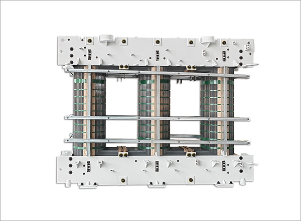
の トランスコア これは、特定の幾何学的形状 (コア タイプまたはシェル タイプ) に組み立てられた薄い積層シリコン スチール シート (通常は厚さ 0.23 mm ~ 0.35 mm) のスタックで、一次巻線によって生成される交流磁束に低磁気抵抗の磁路を提供します。各積層体は薄い絶縁ワニスまたは酸化物層でコーティングされており、隣接するシート間に渦電流が流れるのを防ぎます。この積層がないと、交流磁場によって固体鋼コア内に大きな循環電流が誘導され、電気エネルギーが有用な磁束ではなく熱に変換されます。この効果は渦電流損と呼ばれ、変圧器が熱的に許容できなくなり、非常に非効率になります。
渦電流損失に加えて、変圧器コアはヒステリシス損失の影響を受けます。この損失は、ケイ素鋼内の磁区が交流磁場によって再調整されるたびにエネルギーが熱として放散され、これは変圧器の動作寿命全体にわたって継続的に 1 秒あたり 50 回または 60 回発生します。最新の結晶配向シリコン鋼コアは、ヒステリシス損失を最小限に抑えるために結晶方位を慎重に制御して製造されていますが、数十年にわたる磁気サイクル、熱応力、および機械的振動の累積的な影響により、コアの積層絶縁が徐々に劣化し、積層の配置が変化し、コア損失が徐々に増加して、トランスの効率が低下し、動作温度が上昇する可能性があります。この劣化メカニズムを理解することは、変圧器の保守プログラムにおいてコアの電気パラメータの定期的なテストがなぜそれほど重要なのかを理解するための基礎となります。
電気試験を実行する前に、変圧器を徹底的に目視および物理的に検査することで、その後の電気試験の範囲と緊急性を判断するための定性的な情報が得られます。油入配電変圧器の場合、目視検査は外部タンク アセンブリと、メンテナンス停止中にアクセスが許可される場合はコアとコイル アセンブリの両方を対象とします。
配電変圧器の電気試験では、コア、巻線、絶縁システムの状態に関する定量的なデータが得られます。以下のテストは、特にコアの状態の評価に関連しており、包括的な変圧器検査プログラムの一部である必要があります。
の core insulation resistance test — also called the core ground test or core megger test — measures the insulation resistance between the transformer core and the tank (ground). On a healthy transformer, the core is insulated from the tank everywhere except at the single intentional grounding point. The test is performed by isolating the core ground lead (if the transformer design brings it out to an external terminal), applying a DC test voltage (typically 500 V or 1,000 V from an insulation resistance meter — a "megger"), and measuring the resulting resistance. A healthy core will typically show insulation resistance values in the range of hundreds of megaohms to several gigaohms. Values below 1 MΩ indicate a fault — either a second unintended core-to-tank contact point (a "shorted core" condition) or severe moisture contamination in the core lamination insulation. Shorted cores cause circulating currents that generate localized heating detectable by thermal imaging or dissolved gas analysis but not always by winding resistance or turns ratio testing alone.
の no-load loss test — also called the excitation loss or iron loss test — measures the power consumed by the transformer core when rated voltage is applied to the primary winding with the secondary open-circuited. Under no-load conditions, the only power drawn from the supply goes into overcoming the core's hysteresis and eddy current losses, plus a small amount of copper loss in the primary winding (which is subtracted or negligible at rated voltage). The no-load loss is measured in watts or kilowatts and compared to the manufacturer's factory test report value for the same unit. An increase in no-load loss above the factory baseline of more than 10 to 15% indicates core deterioration — typically from inter-laminar insulation breakdown causing increased eddy current paths, or from core damage that has altered the flux distribution within the core. This test requires energizing the transformer at rated voltage and frequency, so it is performed during scheduled maintenance outages when the transformer can be connected to a power supply while remaining isolated from the distribution network load.
の excitation current test is performed simultaneously with the no-load loss test and measures the current drawn by each phase of the primary winding under rated voltage no-load conditions. The excitation current (also called magnetizing current) represents the current required to establish the magnetic flux in the core. In a healthy three-phase transformer, the excitation current in the outer limbs (legs) of the core is typically higher than in the center limb due to the asymmetry of the core magnetic path lengths — an expected and normal pattern. Significant asymmetry beyond the expected pattern, or a marked increase in excitation current on one or more phases compared to factory baseline values, can indicate localized core damage, shorted turns in the primary winding, or physical damage to the core geometry from transportation or seismic events. Comparing test results to the original factory test report is essential for meaningful interpretation — excitation current values in isolation have limited diagnostic value without the baseline reference.
変圧器絶縁油の溶存ガス分析は、鉄心関連の故障を含む、油入配電変圧器の進行中の故障を検出するための単一の最も強力な診断ツールです。変圧器タンク内で異常な熱的または電気的活動が発生すると、その原因がコア積層板の短絡、部分放電、アーク放電、または巻線の故障のいずれであっても、そのエネルギーによって周囲の絶縁油とセルロース絶縁体が分解されて特徴的なガス混合物になります。これらのガスは油に溶解しており、油サンプルを実験室で分析することで抽出および定量できます。
| ガス | 一次情報源 | 障害の表示 |
| 水素(H₂) | 油の分解 | 部分放電、コロナ、低エネルギーアーク放電 |
| メタン (CH₄) | 油の分解 | のrmal faults (low temperature) |
| エチレン (C₂H₄) | 油の分解 | のrmal faults (high temperature, >300°C) |
| アセチレン (C₂H₂) | 油の分解 | 高エネルギーアーク放電 (>700°C) — 緊急故障 |
| 一酸化炭素(CO) | セルロース分解 | のrmal degradation of paper insulation |
| 二酸化炭素 (CO₂) | セルロース分解 | 紙絶縁体の通常の老化または過熱 |
炉心固有の故障検出の場合、中程度のエチレンを伴う水素とメタンの上昇(比較的低温での熱故障に関連するパターン)は、油内に局所的なホットスポットを生成する短絡した炉心の積層の特徴的な兆候です。 IEC 60599 および IEEE C57.104 規格は、DGA 結果から障害タイプを診断するための解釈フレームワーク (Duval Triangle および主要なガス比メソッドを含む) を提供します。時間の経過に伴う DGA 結果の傾向 (現在の結果と以前のサンプルを比較) は、単一のサンプルよりも診断上の価値が高くなります。これは、ガス発生率が、アクティブな障害と過去の障害を識別する際に絶対ガス濃度と同じくらい有益であるためです。
上記のコア固有のテストは変圧器のコアに直接対応していますが、変圧器のチェック方法を完全に評価するには、コアに加えて巻線と絶縁システムを評価する追加のテストが必要です。これらのテストは補完的な診断情報を提供し、包括的な変圧器検査の標準コンポーネントです。
巻線の絶縁抵抗試験では、高電圧巻線と低電圧巻線の間、および各巻線とアース (タンク) の間の DC 抵抗を測定します。中高圧配電用変圧器の試験は、絶縁抵抗計を使用して2,500Vまたは5,000Vで実施されます。分極指数 (PI) は、1 分間の絶縁抵抗測定値と 10 分間の絶縁抵抗測定値の比であり、瞬間抵抗だけではなく絶縁体の誘電吸収特性を反映するため、単一点の抵抗値よりも確実な絶縁状態の指標となります。一般に、PI が 2.0 以上であれば、許容可能な絶縁状態を示します。 1.5 未満の値は、湿気による汚染または重大な絶縁劣化を示唆しており、変圧器を使用に戻す前にさらなる調査が必要です。
の turns ratio test verifies that the ratio of primary to secondary turns — and therefore the transformer's voltage transformation ratio — matches the nameplate specification within acceptable tolerance (typically ±0.5% for distribution transformers). The test is conducted using a transformer turns ratio (TTR) meter that applies a low-voltage AC signal to the primary winding and measures the resulting secondary voltage, computing the turns ratio directly. Deviation from the nameplate ratio indicates shorted turns in either the primary or secondary winding — a condition that increases winding copper losses, reduces voltage regulation performance, and if progressive, will eventually lead to thermal failure of the shorted turn region. Turns ratio testing is quick and non-destructive, and it provides a definitive check on winding integrity that complements the insulation resistance and DGA data.
既知の温度で各巻線の DC 抵抗を測定し、工場でのテスト データ (同じ基準温度に補正) と比較することで、タップ チェンジャの接点、リード接続、またはブッシング端子での高抵抗接続、および並列巻線経路の開回路状態が特定されます。 DC 抵抗測定は通常、ミリオームレベルの抵抗を正確に測定できる高精度マイクロオーム計を使用して行われます。いずれの段階においても、補正されたベースラインを超えて 2 ~ 3% を超える抵抗の増加は、接続に問題が発生していることを示しており、負荷がかかると発熱し、対処しなければ、接続不良や隣接する絶縁への熱損傷につながります。
の frequency and scope of transformer testing should be determined by the unit's criticality, age, loading history, environmental exposure, and the results of previous inspections. The following framework provides a practical starting point for scheduling distribution transformer inspections.
配電変圧器のチェック、特にそのコアの健全性の評価は、単一のテストではなく、目視検査、対象を絞った電気テスト、およびオイル分析を組み合わせてユニットの状態を一貫して把握する構造化された診断プロセスです。各テストは特定の故障モードまたは劣化メカニズムに対応しており、コア絶縁抵抗、無負荷損失、励磁電流、DGA、および巻線テストの結果を組み合わせることで、メンテナンスの優先順位、負荷管理、および残りの耐用年数について情報に基づいた決定を下すために必要な包括的なデータが得られます。変圧器の動作寿命にわたって体系的かつ一貫して適用されるこのテスト プログラムは、配電システムで最も資本集約的なコンポーネントの 1 つの信頼性と寿命を保護するために利用できる最も効果的な投資です。
 +86-523 8891 6699
  +86-523 8891 8266
  info@tl-core.com
  中国江蘇省台州市良緒街第三工業団地1号

 中文简体
中文简体


